Note: This page is best viewed with a browser that supports MathMl and HTML5 for
viewing the formulae correctly.
Torsion and Fracture Mechanics
Concrete and fracture mechanics
Fracture mechanics is a well known approach for relatively
homogeneous materials such as steel. Extensive literature and examples
based on decades of research are available for these materials. There
have been many attempts to include concrete in the family of materials
where fracture mechanics is applicable. From a practitioners point of
view, they have largely been unsuccessful due to the post-crack
behaviour of concrete. As a very brittle material concrete has minimal
post-crack strength. Torsion capacity calculations are written into
design codes around concrete in tension being cracked and offering no
strength.
Fibres change post-crack behaviour
Fibres supplied by manufacturers for general use in the construction industry can arrest and re-distribute cracking stresses in concrete. It is important to note that fibres do not prevent cracking. Fibres at workable dosages are effective when concrete tensile stresses reach and exceed the tensile capacity of concrete. This far, there are no fibres available on the market for general use, in workable quantities and economically competitive that can prevent cracking. Therefore current “state of the art” fibres cannot replace primary tensile reinforcement. Nevertheless there is ongoing development in this area, and research suggests specific types of structures may lend themselves to using fibre.Fibres are very useful in applications where there are indirect tensile stresses. They significantly improve ductility and deformation capacity of plain concrete. Examples include shear, torsion and bearing (bursting). In this paper, torsion will be used as an example where fracture mechanics provides a theoretical framework and a new approach.
Current practice for torsion design
There are design guides, codes and standards available to assess torsion capacity of conventionally reinforced concrete sections, that is, with longitudinal bars and stirrups. The design capacities are almost entirely based on testing and empirical relationships developed from test results.For a plain reinforced concrete section (rectangular, square or circular) the current approach is two-fold. First, compare the applied torsion with the cracking torsion. If the applied torsion is less than the cracking torsion by a suitable margin then no more need be done. Second, if the applied torsion exceeds the “safe” factored cracking torsion then assume the section is completely cracked. The fully cracked section together with longitudinal reinforcement and stirrups form a three dimensional “space frame” of struts and ties to resist applied torsion.
Concrete members tend to be solid (beams and columns) or large hollow segments (bridges). For solid members warping can be ignored and for hollow bridge girders the designer may need to consider warping depending on the girder proportions. The following discussion relates to “free torsion”, that is, simple torsion with no shear, bending or restraints.
Torsion and fibre reinforced concrete
In the case of steel fibre reinforced concrete the focus is on the cracking torque as an increase in capacity can be expected. Using the same fracture mechanics approach as was adopted for shear capacity the torsion capacity will increase due to tensile post-crack stresses due to the presence of fibre.The relationship between the torsion force and maximum torsion stress is;
where u is a geometric parameter based on the shape of the
cross-section. There are many references available for geometric
parameters for a variety of cross-sections. “Theory of Elasticity” by
Timoshenko & Goodier and “Roark’s Formulas for Stress &
Strain” are recommended.
As with shear capacity, a multiplier kG that reflects post-crack strength can be adopted for torsion capacity such that;
As with shear capacity, a multiplier kG that reflects post-crack strength can be adopted for torsion capacity such that;
Fracture Mechanics
Fracture energy and characteristic length
Fracture energy Gf can be determined for any material providing the post-crack tension behaviour is understood. A parameter, characteristic length lch , can be derived from the fracture energy. Hillerborg [1] invented the characteristic length defined as:It has the following physical meaning: If a sample is under
uniaxial tension and the material has a linear softening curve, the
maximum length for getting stable fracture under displacement
control over this length is equal to twice the characteristic
length. This can be shown by comparing fracture work and elastic
energy in a sample.
Torsion cracks are also the result of indirect tension stresses and the mechanism is arguably the same. Once micro-cracking commences stresses are aligned parallel and perpendicular to the cracks. The effect of fibres is to provide restraint in the perpendicular direction thus enhancing aggregate interlock that resists stresses parallel with the crack.
Steel fibres can therefore be said to enhance the toughness of concrete and it is possible to postulate a relationship between combined stresses, including indirect tension, and characteristic length. Hillerborg suggested a dependency of shear capacity upon characteristic length as shown in the following equation.
With a bi-linear stress-displacement model (or softening curve) it is possible to calculate Gf and lch for steel fibre reinforced concrete. With these parameters a proportional function can be developed to calculate ultimate shear capacity.
Zink [4] developed a proportional function kG that correlated well with 233 test results on conventionally reinforced and prestressed concrete sections where:
In the absence of test results of SFRC members in torsion, this factor developed for shear capacity can be adopted for torsion. It would be a “first estimate” based on the similarity of mechanisms associated with shear and torsion, but would need to be verified by testing of a range of cross-sections, concrete strengths and fibre types.
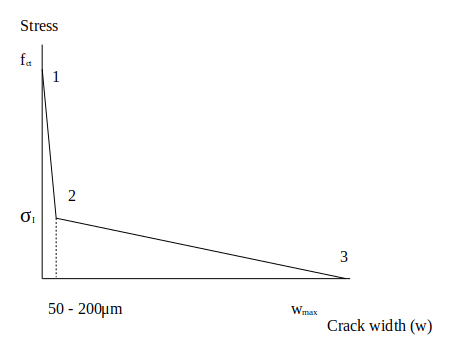
• Point 1 represents the initial tensile stress limit of the concrete matrix.
• Point 2 is reached at very small crack openings (micro-cracking) of 50μm. Until this point, only concrete is resisting tensile stresses. Steel fibres begin to be mobilised.
• Point 3 is somewhat arbitrary, but is conservatively selected to be less than the opening at which fibres are effective. Based on direct tension testing at Victoria University this should, conservatively, be no greater than 5mm to 10mm to ensure a linear curve is valid.
Characteristic length lch

Bi-linear softening curve
Torsion capacity model
Work by Gustaffson [2] and Hillerborg [3] indicates a dependency of shear capacity on the tensile strength of concrete ft , beam depth d, the reinforcement ratio ρ, span to depth ratio and the characteristic length lch . This also seems intuitively correct as shear cracks are the result of indirect tension stresses.Torsion cracks are also the result of indirect tension stresses and the mechanism is arguably the same. Once micro-cracking commences stresses are aligned parallel and perpendicular to the cracks. The effect of fibres is to provide restraint in the perpendicular direction thus enhancing aggregate interlock that resists stresses parallel with the crack.
Steel fibres can therefore be said to enhance the toughness of concrete and it is possible to postulate a relationship between combined stresses, including indirect tension, and characteristic length. Hillerborg suggested a dependency of shear capacity upon characteristic length as shown in the following equation.
With a bi-linear stress-displacement model (or softening curve) it is possible to calculate Gf and lch for steel fibre reinforced concrete. With these parameters a proportional function can be developed to calculate ultimate shear capacity.
Zink [4] developed a proportional function kG that correlated well with 233 test results on conventionally reinforced and prestressed concrete sections where:
In the absence of test results of SFRC members in torsion, this factor developed for shear capacity can be adopted for torsion. It would be a “first estimate” based on the similarity of mechanisms associated with shear and torsion, but would need to be verified by testing of a range of cross-sections, concrete strengths and fibre types.
Softening curve
A bi-linear softening curve (refer to figure 1) has been adopted to model concrete matrix behaviour when the concrete matrix passes through peak stress capacity. Three points on the bi-linear softening curve are defined based on test data. They will be derived in detail below, however referring to the chart below, in summary :• Point 1 represents the initial tensile stress limit of the concrete matrix.
• Point 2 is reached at very small crack openings (micro-cracking) of 50μm. Until this point, only concrete is resisting tensile stresses. Steel fibres begin to be mobilised.
• Point 3 is somewhat arbitrary, but is conservatively selected to be less than the opening at which fibres are effective. Based on direct tension testing at Victoria University this should, conservatively, be no greater than 5mm to 10mm to ensure a linear curve is valid.
Torsion Capacity of SFRC Based on Fracture Mechanics
Fracture energy and characteristic length
Fracture energy GfCharacteristic length lch

Bi-linear softening curve
| Crack width range | Note |
| 0 to 50μm ~ 200μm | Concrete only |
| 200μm to wmax | Fibre only |
Calculate point 1
Adopt
This is the average tensile stress and can be reduced to the 5% fractile (see notes below).
Calculate point 2
Fibre alone provides tensile capacity.
Where
◦ 0.3 is a measure of fibre effectiveness due to 3-D orientation.
◦ ηVOL is steel fibre proportion of matrix (volume).
◦ η is steel fibre dosage kg/m3
◦ ρs density of steel 7850 kg/m3
◦ στ = fibre stress at bond failure (pullout)
Direct tension tests of steel fibre reinforced concrete indicate that moderate to high performance fibres will have tension stress exceeding 70% of their yield strength as they are pulled out post-crack. Therefore στ would typically be around 800 to 1100 MPa. For very high performance steel fibres the stress would be higher.
Calculate point 3
For consistency, can adopt an approach that all steel fibres are pulled out of the matrix when :
however, in reality there will still be some fibres, less than half the dosage (say) that would be holding load. This will also depend on fibre type. Some fibres snap the end anchorage and easily slide out with very little residual capacity. Spade-end fibres have sufficient strength to work their way through the cement paste, deforming as they progress, and continue to hold considerable load. Hook-end fibres have sufficient strength to “un-kink” the hook-end during pull-out, but once the fibre has withdrawn past the last bend it has very little residual strength.
For these reasons, and because the final value of wmax beyond a certain value has little effect on the calculation of Gf, wmax can be a range of values. A conservative range for torsion would be :
For the purpose of calculating torsion capacity, one could adopt a crack width that reflects a best “guess” beyond which torsion is no longer viable in a semi-elastic manner. This is highly likely to depend on aggregate type and size and requires more research, but at this stage very small crack widths are recommended.
Fracture energy
Fracture energy Gf is the area under the softening curve. Characteristic length lch is calculated as follows :
Torsion capacity
Torsion capacity Tf can be calculated using an expression with area above the neutral axis, average tensile stress at the limit state and a multiplier effect based on the fracture zone where:therefore
The maximum torsion stress τmax can be taken as the rupture stress of concrete, or modulus of rupture. There are many suggestions in references and codes for the rupture stress. Some references suggest that concrete capacity to resist tensile stresses due to torsion is less than that allowed for shear. Based on direct tension tests the Eurocode 5% fractile strength is recommended.
Example – Torsion capacity of a rectangular beam
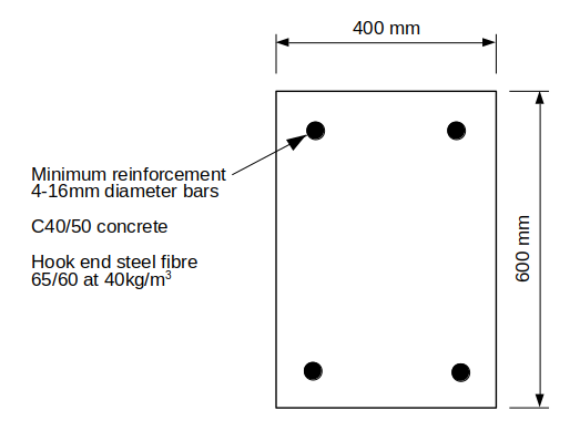
Cracking torsion is calculated using the elastic approach and a modified approach for SFRC for the cross section shown below.
From “Theory of Elasticity” by Timoshenko & Goodier;
where α is a constant based on cross-section dimensions with x as the smaller dimension and y as the larger dimension. The torque therefore calculates to:
where
therefore
and cracking torque is
Fracture mechanics multiplier
The multiplier due to adding steel fibre is calculated using the equations described above. As the intention is to limit micro-cracking so that aggregate interlock persists, a very small crack opening of just 0.5 mm was selected to calculate fracture energy Gf and fibre stress was also limited to reflect the very small crack opening.
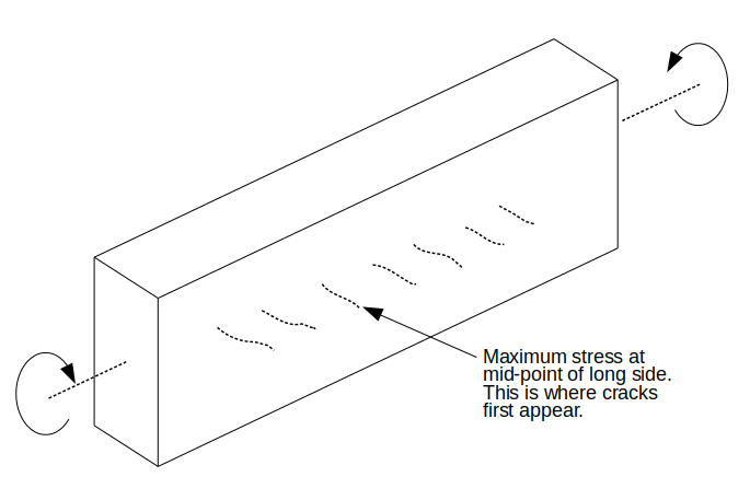
For rectangular sections, observations and measurements indicate that maximum torsion stresses are on the longest side. This is also where the first cracks appear. Therefore the effective depth d used to calculate kG is based on the smaller section dimension. In this case d = 400 mm subtract distance from outer surface to centre of the bar.
Based on these parameters
and
Conclusion
This article describes the approach used to obtain the torsion cracking moment using the elastic method. Cracking torque is expected to increase due to the presence of steel fibres in the concrete matrix. Some quite conservative parameters were used to calculate the increased strength.To our knowledge there have been no tests of steel fibre reinforced concrete sections in pure torsion. Such a testing program would be valuable research to verify if the theoretical approach described above is valid or needs to be adjusted. As steel fibre reinforced concrete has post-crack capacity it is thought fracture mechanics will be valid and provide a deeper understanding of torsion.
From a practical point of view, as steel fibre reinforced concrete is increasingly being used in structural elements there will also be load circumstances and structure geometry where torsion becomes important. As is well understood, concrete structures are subject to combined forces including bending, shear and torsion. Further testing of combined forces would also be useful to confirm the principle of super-position continue to apply.
Research Initiatives