
SFRC Pavement Testing
INTRODUCTION
Steel fibre reinforced concrete (SFRC) has been successfully used in pavement slabs for a number of years. There are reference manuals1 that describe design and construction methods. Design and construction practitioners have over a number of years developed a better understanding of how to construct SFRC pavements. Many aspects of the successful performance of SFRC have come about as a result trial and error, intuitive “guesses”, observations of slab performance in varying environmental conditions, increasing confidence with the robustness of the material, and a good grasp of important pavement parameters.
Core samples were taken from a SFRC industrial pavement approximately 10 years after construction. The internal slabs were placed under cover as large single pours of varying size. Amongst the largest were panels 35 m x 30 m. The slab was nominally 160 mm thick and the SFRC had the following documented specifications;
| Concrete cylinder strength at 28 days | 40 MPa |
| Minimum cementitious content | 320 kg/m3 |
| Maximum concrete shrinkage | 650 microstrain |
| Steel fiber | 30 kg/m3 Dramix 65/60 manufactured by Bekaert |
The slab was constructed on a prepared granular manufactured sand sub-base, compacted and rolled to approximately the same profile as the finished slab surface. A layer of plastic was placed on the sub-base to act as a moisture barrier during curing and reduce the friction coefficient when shrinkage takes place. The slab panels were cast directly against each other at nominated construction joints. Slab joints were bridged using plate dowels, free to move on one side, to transfer vertical shear and minimise differential movement, especially from rolling loads. Wherever slab panels abutted other structures, such as columns, walls and pits, the slab was detailed to ensure there was movement capacity as the concrete shrinks. There were no thickened edges or thickened footing sections of the slab. This was to prevent “anchors” being formed that could resist shrinkage and induce unnecessary stresses in the slab. There was no conventional reinforcement in the form of steel mesh or reinforcing bars.
Concrete was placed quickly and efficiently using laser screeds to uniformly spread the SFRC. Heavy duty finishing machinery was used to provide the finished surface at the earliest opportunity and a spray seal for curing was applied on the same day. A benefit of using SFRC is that concrete trucks can drive directly onto the sub-base to deliver wet concrete as there are no reinforcing bars. This increases the speed of delivery and ensures any opportunities for “cold joints” are minimised, especially as poker vibrators are used for compaction and mixing at interfaces.
SAMPLES RECOVERED FROM PAVEMENT SLAB
Six core samples were taken from one slab panel. The cores were 80 mm in diameter and varied in height from 165 mm to 178 mm. The slab was generally slightly thicker than the 160 mm specified on the engineering drawings. After extraction, the core holes were filled with a high early strength non-shrink grout to ensure factory operations were not affected.
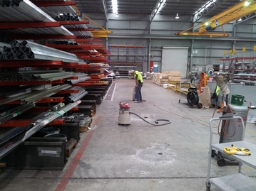 Core drilling in the existing factory |
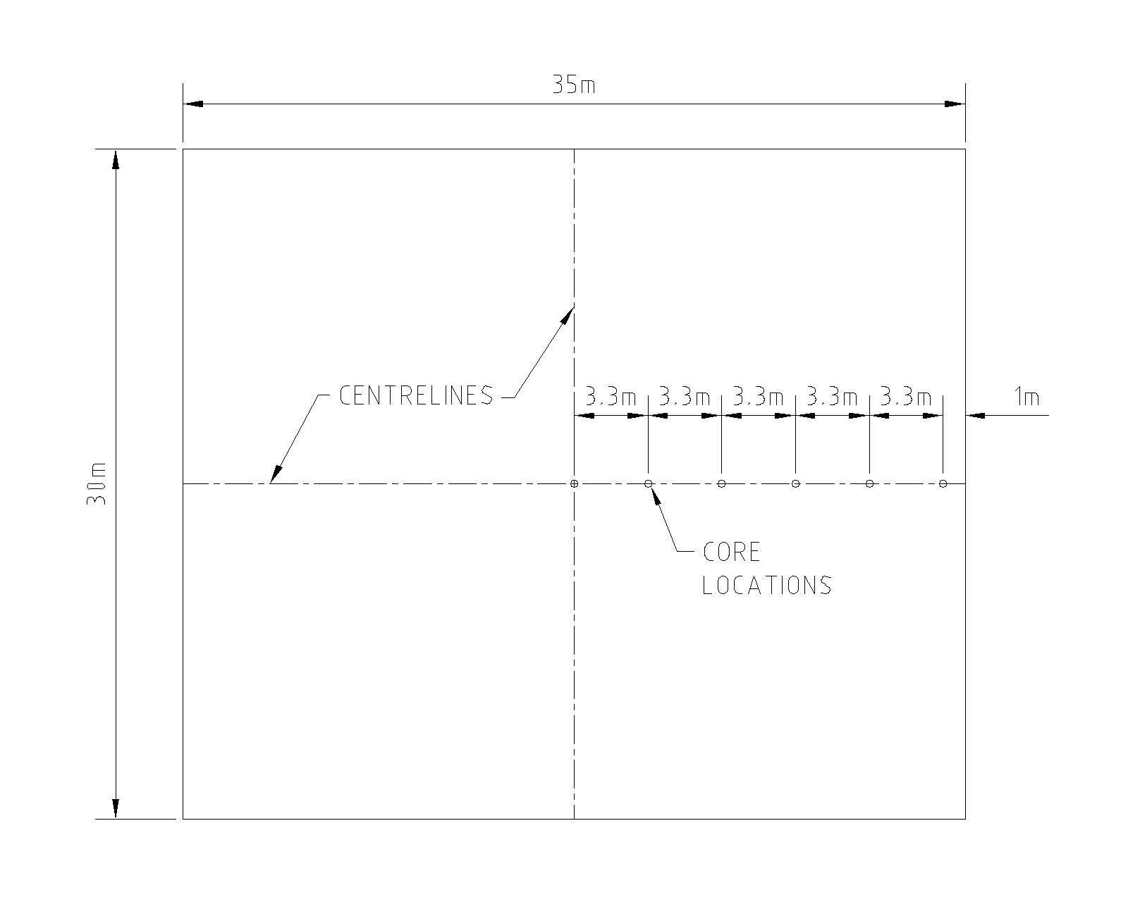 Core locations selected to assess effect of shrinkage combined with wheel loads and other live loads |
OBSERVATIONS DURING SAMPLING
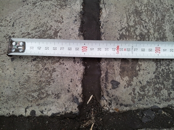 |
The pavement slab had no saw-cuts even though slabs were cast as large as 35 m x 30 m. There were no visible cracks due to live loads or shrinkage in any panels. All shrinkage was taken up at the dowel pour joints. The joints had been well maintained with joint filler providing lateral "shoulder" support to the edges of the concrete slab. Joints have opened due to shrinkage by approximately 20 mm as shown in the picture. |
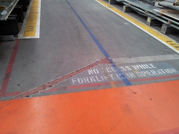 |
Rebates had been cut into the slab for services cables and
filled in with some type of grout. |
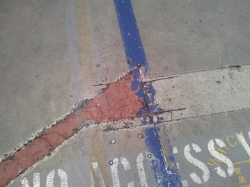 |
Note there are no cracks emanating from the saw-cuts even
though terminations are not favourable to the slab. |
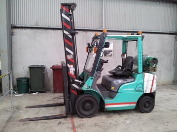 |
Typical forklift used to move roles of steel weighing up to
1.5 tonne |
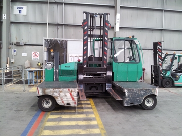 |
Side loading forklift for heavy steel elements manufactured
at the factory |
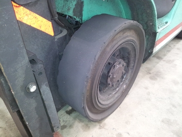 |
Hard rubber forklift wheels. The contact patch of these
types of wheels is quite small in comparison with pneumatic
wheels. Combined with high load capacity, these types of
wheels are usually the cause of pavement failures. In this
case the pavement has performed satisfactorily as there were
no signs of failure after 10 years. |
DISCUSSION
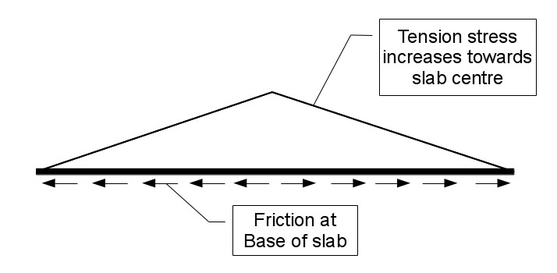 |
This (much simplified) two-dimensional representation of the expected shrinkage stress illustrates the expected increase in shrinkage stresses towards the centre of the slab. Tension is caused by accumulating friction at the interface with the underlying plastic membrane. |
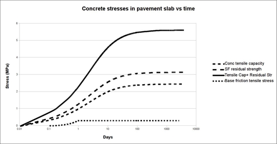 |
Based on the simplified shrinkage model it can be
demonstrated that stress caused by base friction (as this is
the only restraint on shrinkage) is significantly lower than
the tensile stress capacity of the slab, especially with steel
fibre added. Base friction increases during the first day of
curing until the friction coefficient is reached. Thereafter
tension remains constant for the life of the pavement. It has been speculated that creep relaxation would reduce the "locked in" tension over time. This indicates there is sufficient tensile capacity in the SFRC slab with adequate capacity for bending and shear stresses due to imposed live and thermal loads. |
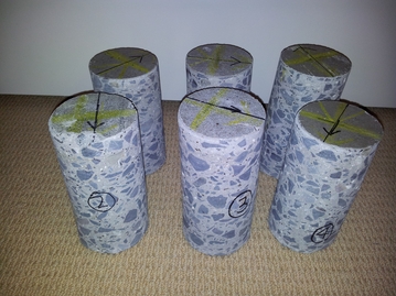 |
Concrete cores 80 mm diameter taken from the pavement slab |
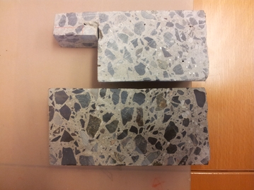 |
The cores were cut suitable for taking micro-slices to view under high magnification |
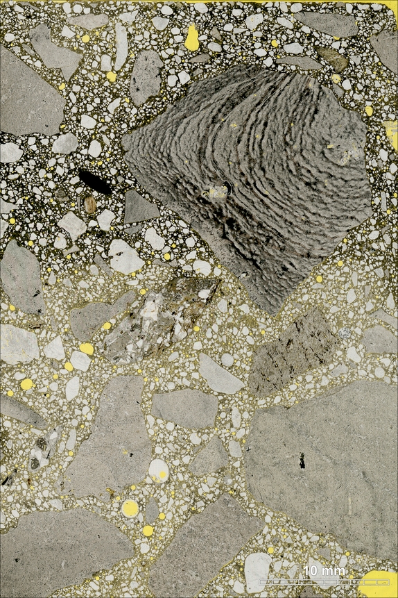 |
Photo of the thin section produced from core number 3. The
surface of the slab can be seen at the top of the photo. Prior to preparation of the thin section, the concrete was impregnated with epoxy that included an added fluorescent dye (fluoresceine) that gives the epoxy a yellow colour. Carbonated cement paste appears dark. |
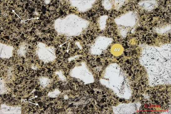 |
This photo shows a part of the concrete thin section under
high magnification by the microscope. Air voids (AV) occur sparsely. Fine aggregates are seen as white particles (AG). Portland cement is seen as small dark particles (PC) in the cement paste. |
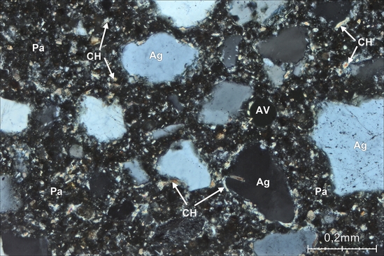 |
This photo shows the same part of the thin section as the
photo above, but another microscope technique has been used. The cement paste appears as a dark uncarbonated mas (Pa) with coloured crystals of calcium hydroxide (CH). The fine aggregates (AG) consist mainly of mineral quartz. Air voids (AV) as before. |
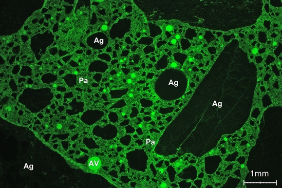 |
This photo shows a part of the thin section seen in
ultra-violet light that activates the fluorescent dye in the
epoxy the concrete was impregnated with. Nonporous areas such as the particles of aggregate (Ag), are depicted dark, whereas porous areas such as air voids (AV) and cement paste are depicted in a lighter colour. |
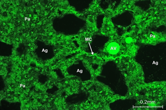 |
This photo shows a part of the thin section area from the
above photo, but at higher magnification. In the cement paste (Pa) only very fine micro cracks (MC) with crack width less than 0.005 mm are seen. Fine aggregates (Ag) and air voids (AV) are also visible. |
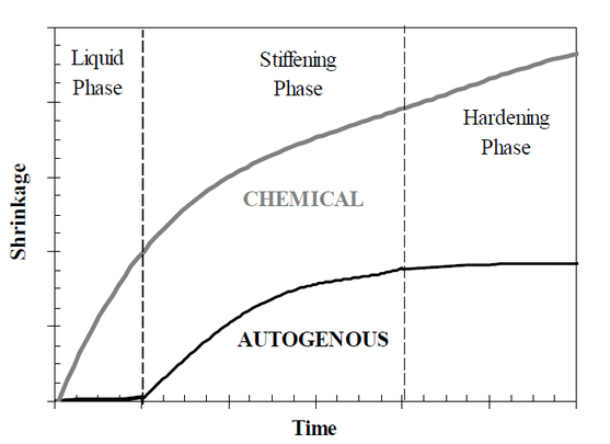 |
There are three types of
shrinkage. This generic chart indicates the time lines
associated with the different types. Autogenous shrinkage: Early age shrinkage during hydration. Low water-cement ratio concrete is particularly susceptible. Drying shrinkage: Longer term shrinkage due to loss of capillary water. Plastic shrinkage: Volume change during the first hours of early age reactions. Fresh concrete in liquid and skeleton formation stages. |
Millions of square metres of fibre reinforced concrete pavement slabs have been completed in numerous locations in many countries. In both internal and external environments. The purpose of this study was to assess the microscopic structure of concrete in a pavement that had provided years of service without any failures or signs of deterioration.
The main conclusions that can be drawn:
- A well prepared site and a good concrete mix with fibres that is well placed will perform satisfactorily.
- There is no discernable difference in the micro-structure of the concrete throughout the pavement.
- Stresses due to shrinkage are well within the capacity of the concrete.
- Minimise base shrinkage by using a leveled sub-base and plastic to reduce the coefficient of friction as much as possible.
The reader is spared from the detailed engineering analysis, however please make contact if you would like further information.
Research Initiatives