
Synthetic fibre reinforced concrete precast pit
Introduction
Three dimensional structures with a complex failure mechanism can benefit from the addition of fibre. Precast underground pits are indicative of "real world" structures. In this case, conventional reinforcement was completely eliminated and the pits are reinforced with synthetic fibres. This works very well in many cases since it is rare to have simple two dimensional forces such as pure bending or pure shear acting in a structure.
Five polypropylene fibre reinforced concrete pits were tested. The purpose of the testing was for compliance with local codes. The pits were 2100mm deep and 1200mm x 1200mm plan dimensions. Load testing was conducted on each pit to determine the load capacity of the side wall when subjected to concentrated lateral load. All five pits were tested in the same manner with the line of action of load positioned 300mm from the top edge of the pit and symmetrically midway between the vertical walls. Testing was conducted by applying an initial proof load for five (5) minutes followed by a continuous ramp were the load was progressively increased until failure of the pits was visibly evident.
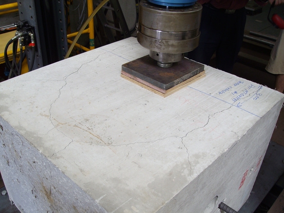
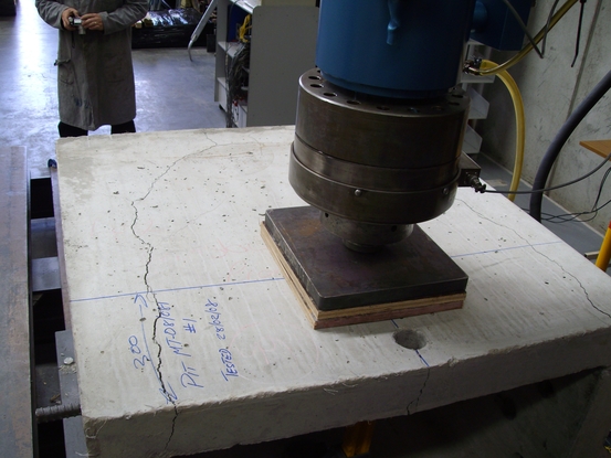
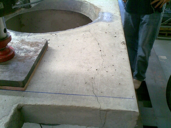
Test Load
The test load was calculated
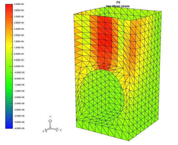
based on a finite element analysis of the pit. Two load cases
were modelled, the ultimate design pressures caused by earth
pressure, and a plate load. The stresses were then calibrated
so the plate load would induce the same centre panel stress as
the field applied pressures. The calculated pressures include
earth and passing heavy vehicle loads. Using this approach the
calibrated plate load was 25.2kN, however 29kN was
conservatively adopted as the proof load.
Based on the finite element analysis the plate load causes lower corner stresses than midspan stresses. Applying pressures to just one side, with no pressure on the other three sides, also achieves the same result. Another load case with the design pressures on one side and earth pressure on the other three sides did reduce the midspan stresses and increase corner stresses slightly. The peak lateral pressure is near the top of the pit (approximately 300mm down) and is caused by nearby wheel loads. Other sides have little earth pressure at such a shallow depth. This resulted in less severe stresses so is not the worst case. Also there is some coincident method in comparing similar stress regimes. Nevertheless this could be considered an added, albeit small, level of conservatism.
During testing the plate proof load was held for 5 minutes, then load was applied until failure when a peak load is recorded. Loading was continued until approximately 15mm of displacement was achieved. This was to measure post-crack performance of the pits.
Precast concrete
• Concrete Strength f’c : 50MPa (Special)
• Polypropylene Fibre Dose Rate: 4kg/m3
Test Procedure
Proof Load Test
Proof load testing was conducted by applying a concentrated load
through a nominal 300mm x 340mm loading pad located
centrally between the pits vertical walls and 300mm in from
the top edge of the pit. The nominated proof load of 29kN
was applied for five (5) minutes during which time the pit
was visually monitored for signs of cracking. Deflection of
the loaded wall was recorded using a linear potentiometer
(see Fig.3) positioned inside the pit and reacting directly
beneath the midpoint of the loading plate.
Ultimate Load Test
Ultimate load testing was conducted in the same manner as
previously described, however the application of load was
continued until cracking in the pits was detected and the
consequential reduction of the applied load was evident.
Test Observations
All Pits
Visual inspection of the five (5) concrete pits carried-out
with the 29kN proof load applied did not reveal any visible
cracking in the pit’s loaded wall or adjoining side walls.
Pit No. 1
The peak pressure recorded was 780kPa (79.6kN) occurring at
the first peak. Cracking of the pit occurred in an abrupt
manner running along both side walls for approximately
1100mm transferring into the loaded wall and terminating at
the pipe penetration. A flexural crack running from the top
of the pit to the pipe penetration directly beneath the
loading platen was also observed.
Pit No. 2
The peak pressure recorded was 553kPa (56.41kN). The first
peak load of 52.3kN coincided with cracking of the pit’s two
side walls for approximately 400mm transferring into the
loaded wall and terminating at the pipe penetration. A
flexural crack located centrally beneath the loading platen
and running from the top of the pit to the pipe penetration
was also observed.
Pit No. 3
The peak pressure recorded was 918kPa (93.62kN). As with Pit #2
the first peak load of 85.1kN coincided with cracking. In
this case the cracking was only observed in the loaded wall,
running from the pipe penetration diagonally to the top edge
of the pit.
Pit No. 4
The peak pressure recorded was 684kPa (69.78kN). As with Pit’s #2
& #3 the first peak load of 61.5kN coincided with
cracking. In this case the cracking was observed in the loaded
wall and side wall, running from the pipe penetration
diagonally to the top edge of the pit.
Pit No. 5
The peak pressure recorded was 761kPa (77.67kN). The first peak
load of 61.0kN coincided with cracking of the pit’s two side
walls for approximately 700mm transferring into the loaded wall
and terminating at the pipe penetration. A flexural crack
running from the top of the pit to the pipe penetration
directly beneath the loading platen was also observed.
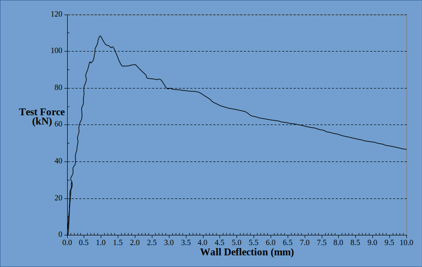
Results and Analysis
The peak loads exceeded the
proof load by factors ranging between 2 and 3.2.
Furthermore, the post-crack load capacity at 10mm
displacement exceeded the proof load by factors ranging
between 1.85 and 2.8 so there is post-crack load carrying
capacity. This is important for consideration in the context
of design codes for concrete structures as synthetic fibre
reinforced concrete pits would be considered as plain
concrete. A typical code comment would be;
“Plain concrete shall be used only for members in which cracks will not induce collapse.”
Any concrete member, be it reinforced with conventional steel bars or fibres will eventually collapse when sufficient displacement is applied, however large displacements will redistribute loads. Arguably with concrete pits and the nature of applied loads a displacement of 10mm to 15mm on one face would sufficiently redistribute loads through the ground and very little additional displacement takes place. The test results indicate there is a factor of safety of two, which is over and above limit state factors that are normally applied.
An analysis of the crack pattens was also completed in an attempt to provide a useful tool for designers in future. Based on measured crack pattens and post-crack load capacity a plastic analysis approach was adopted. Effectively, three hinges formed and each can be considered to have the same plastic moment capacity. The plastic hinge moment capacity per linear metre is tabulated in the calculations. In future, designers can selected the shortest possible crack lengths that would induce pit failure and calculate the load capacity for a variety of pit shapes and pressures.
Conclusion
The tests and analysis demonstrate that synthetic fibre reinforced concrete pits can comply with concrete structures codes and have also provided useful information for future design of similar three dimensional structures. This work has demonstrated that synthetic fibre reinforced concrete can be extended to a wide range of new applications. With the right "know how" and experience it is possible to make an appraisal of new innovations and applications. A test program together with sound engineering analysis will enable innovative new applications to be extended to a range of structures.
Research Initiatives